The Effect of Nano-Structured Nickel Coating on Reducing Abrasive Wear of Tillage Tine
Article Information
Niloofar Abed1*, Mohammad Ebrahim Bahrololoom2, Mehdi Kasraei1
1Department of Biosystems Engineering, University of Shiraz, Shiraz, Iran
2Department of Material Engineering, Shiraz University, Shiraz, Iran
*Corresponding Author: Niloofar Abed, Department of Biosystems Engineering, University of Shiraz, Shiraz, Iran
Received: 08 July 2019; Accepted: 23 July 2019; Published: 26 July 2019
Citation:
Niloofar Abed, Mohammad Ebrahim Bahrololoom, Mehdi Kasraei. The Effect of Nano-Structured Nickel Coating on Reducing Abrasive Wear of Tillage Tine. Journal of Nanotechnology Research 1 (2019): 059-074.
View / Download Pdf Share at FacebookAbstract
The purpose of this study was comparing three methods of coating, including DC electroplating, pulse electroplating and the electroplasma methods for coating of nickel compounds on pieces carved from high carbon steel material (Ck60). Resistance of the coatings to abrasion was assessed with the criterion of proportion of weight reduction due to abrasion in the farm of operations. The coating made by DC electroplating, improved abrasion resistance in the samples by 30.41%. The coatings made by pulse electroplating on the pieces could improve abrasion resistance relative to raw samples by 55.83%. In the electroplasma method, by formation of coatings that had complex compositions, resistance to abrasion increased up to 90% relative to raw samples. It is noteworthy that such resistance to abrasion was in samples with the 480 HV and average grain size of 38 nanometers. The less the average sizes of grains of nickel Nano-coatings of the structure, the more the hardness and, consequently, the more wear resistance.
Keywords
Wear, Nickel coating, Nano-structure, Electro-plasma, Electroplating
Wear articles Wear Research articles Wear review articles Wear PubMed articles Wear PubMed Central articles Wear 2023 articles Wear 2024 articles Wear Scopus articles Wear impact factor journals Wear Scopus journals Wear PubMed journals Wear medical journals Wear free journals Wear best journals Wear top journals Wear free medical journals Wear famous journals Wear Google Scholar indexed journals Nickel coating articles Nickel coating Research articles Nickel coating review articles Nickel coating PubMed articles Nickel coating PubMed Central articles Nickel coating 2023 articles Nickel coating 2024 articles Nickel coating Scopus articles Nickel coating impact factor journals Nickel coating Scopus journals Nickel coating PubMed journals Nickel coating medical journals Nickel coating free journals Nickel coating best journals Nickel coating top journals Nickel coating free medical journals Nickel coating famous journals Nickel coating Google Scholar indexed journals Nano-structure articles Nano-structure Research articles Nano-structure review articles Nano-structure PubMed articles Nano-structure PubMed Central articles Nano-structure 2023 articles Nano-structure 2024 articles Nano-structure Scopus articles Nano-structure impact factor journals Nano-structure Scopus journals Nano-structure PubMed journals Nano-structure medical journals Nano-structure free journals Nano-structure best journals Nano-structure top journals Nano-structure free medical journals Nano-structure famous journals Nano-structure Google Scholar indexed journals Electro-plasma articles Electro-plasma Research articles Electro-plasma review articles Electro-plasma PubMed articles Electro-plasma PubMed Central articles Electro-plasma 2023 articles Electro-plasma 2024 articles Electro-plasma Scopus articles Electro-plasma impact factor journals Electro-plasma Scopus journals Electro-plasma PubMed journals Electro-plasma medical journals Electro-plasma free journals Electro-plasma best journals Electro-plasma top journals Electro-plasma free medical journals Electro-plasma famous journals Electro-plasma Google Scholar indexed journals Electroplating articles Electroplating Research articles Electroplating review articles Electroplating PubMed articles Electroplating PubMed Central articles Electroplating 2023 articles Electroplating 2024 articles Electroplating Scopus articles Electroplating impact factor journals Electroplating Scopus journals Electroplating PubMed journals Electroplating medical journals Electroplating free journals Electroplating best journals Electroplating top journals Electroplating free medical journals Electroplating famous journals Electroplating Google Scholar indexed journals electrolyte articles electrolyte Research articles electrolyte review articles electrolyte PubMed articles electrolyte PubMed Central articles electrolyte 2023 articles electrolyte 2024 articles electrolyte Scopus articles electrolyte impact factor journals electrolyte Scopus journals electrolyte PubMed journals electrolyte medical journals electrolyte free journals electrolyte best journals electrolyte top journals electrolyte free medical journals electrolyte famous journals electrolyte Google Scholar indexed journals mechanical properties articles mechanical properties Research articles mechanical properties review articles mechanical properties PubMed articles mechanical properties PubMed Central articles mechanical properties 2023 articles mechanical properties 2024 articles mechanical properties Scopus articles mechanical properties impact factor journals mechanical properties Scopus journals mechanical properties PubMed journals mechanical properties medical journals mechanical properties free journals mechanical properties best journals mechanical properties top journals mechanical properties free medical journals mechanical properties famous journals mechanical properties Google Scholar indexed journals nano-nickel articles nano-nickel Research articles nano-nickel review articles nano-nickel PubMed articles nano-nickel PubMed Central articles nano-nickel 2023 articles nano-nickel 2024 articles nano-nickel Scopus articles nano-nickel impact factor journals nano-nickel Scopus journals nano-nickel PubMed journals nano-nickel medical journals nano-nickel free journals nano-nickel best journals nano-nickel top journals nano-nickel free medical journals nano-nickel famous journals nano-nickel Google Scholar indexed journals nanostructured articles nanostructured Research articles nanostructured review articles nanostructured PubMed articles nanostructured PubMed Central articles nanostructured 2023 articles nanostructured 2024 articles nanostructured Scopus articles nanostructured impact factor journals nanostructured Scopus journals nanostructured PubMed journals nanostructured medical journals nanostructured free journals nanostructured best journals nanostructured top journals nanostructured free medical journals nanostructured famous journals nanostructured Google Scholar indexed journals plating articles plating Research articles plating review articles plating PubMed articles plating PubMed Central articles plating 2023 articles plating 2024 articles plating Scopus articles plating impact factor journals plating Scopus journals plating PubMed journals plating medical journals plating free journals plating best journals plating top journals plating free medical journals plating famous journals plating Google Scholar indexed journals
Article Details
1. Introduction
In designing and producing agricultural machines, there are difficulties related to the kinds of materials regarding their mechanical properties such as hardness, wear resistance, toughness and ductility. The problem arises when objects of agricultural machinery are always at the risk of erosion, continuous cyclic loads, wear, corrosion, pulse, etc. This condition limits the diversity of raw materials in the production of agricultural tools. Each tillage has parts that should be like a sharp knife to cut plants and soil debris, as an example. This part in the moldboard tillage is a blade that specific points should be observed in its production to do better work. Blade has wear because of soil properties and the presence of sand, stone and gravel. Blade wear can reduce efficiency and increase the consumption of fuel and energy in the tillage operation. To prevent and reduce wear in their manufacture, methods like surface hardening and plating have been used. Tillage tools should be hard and tough and these two features could not be found in steels at the same time. These opposing properties make difficulties in terms of engineering and designing [1].
Wear is the most important limiting factor of life and performance of cutting tools and other tillage tools. The tillage blades are exposed to severe wear because of cutting the soil and separating it from the ground in an intact way compared with other agricultural tools. Wear of tillage tools is a kind of roaring wear. Roaring wear mechanism is created in contact with each other in the presence of hard particles on one or both surfaces. The hard roughness of the surface can also be the cause of this type of wear [2]. The wear depends on many parameters such as geometry, strength and surface properties. Water can be an important factor in this regard. Increased humidity can increase the wear resistance of the nanostructured materials [3].
Hardness and wear resistance are two important properties of objects that are used in a wear environment. By definition, hardness of a material and its resistance to plastic deformation is localized and has a direct relationship with wear resistance. Nickel electroplating is based on using a nickel anode and applying a direct current to the anode and cathode in an aqueous environment containing nickel ions. Passing a direct current causes anode electrode dissolution in the electrolyte and nickel is coated on the cathode. It has been proved that stiffness can be increased by fine grain size materials, without reducing the flexibility of the material. In nickel nanostructured coatings which have an average grain size of about 100 nm and produced by electroplating method, wear resistance is about 100 to 170 times than nickel coatings with the average grain size of about 100 micrometers. The coefficient of friction of these coatings is about 40 to 50 percent less than conventional nickel coatings [4].
Size and shape of grains in a coating have large effects on the mechanical properties such as hardness. The smaller the grain size of a coating, the friction coefficient will be less. These differences are due to the changing in wear mechanism by changes in the grains size. Wear resistance of a conventional nickel coating is low. However, nickel nanostructured coatings have high resistance against wear. There is a relationship between the shape, grain size of coating and mechanical and physical properties of coating with the conditions of plating that awareness of this relationship makes nano-nickel coating replacement with chromium coating affordable [5].
Pulse plating is a simple, inexpensive and new method to produce a nanostructured electrodeposited coating. The differences between these methods and conventional electroplating is on how to apply current. A direct current is applied continuously and uniformly in electroplating, but the current is applied in the form of pulses in plating. In 1979, Moore [6] investigated the roaring wear resistance on the surface coatings and finally found several results:
- The wear rate achieved in a particular soil, may differ from the wear rates of soils with different amounts of stones and different physical properties.
- The resistance against roaring wear depends on the properties and microstructure of materials such as size, hardness, amount of carbon and chemical composition.
- The resistance against roaring wear on the coated surface may be influenced by coating techniques [6].
Owsiak [7] compared four steal samples in terms of wear rate in the agricultural soils and found that the effects of roaring wear significantly reduce by increasing the amount of carbon in steel and decreasing the length of the blade has a linear relationship with mileage, wear the sharp edges of the blade has a linear relationship with mileage, and wear the sharp edge of blade depends on the mileage, distance from the tip of the blade and soil type. Yilmaz [8] studied the relationship between abrasive wear and erosive wear and AISI 1050 steel surface hardening methods. Conclusion of this experiment was as follows:
- When the layers of ceramic like surface was brittle on the surface of the sample and when the sample was exposed to abrasive wear, because of the contact of particles with each other, tiny cracks have been created on it, which would increase the amount of wear. This has been observed on the samples under the thermochemical treatment, such as denitrification.
- Composite coatings often increased wear resistance. In the case of flame spraying process loss of weight has been reported about 59 and 61 percent, respectively. Also, wear resistance increased about 36/3 percent by adding about 35 percent of powder coating on the objects in the same way. This study examined and compared the effect of nickel nano-structured coatings on reducing wear blade tillage by DC, pulse and electro plasma plating.
2. Materials and Methods
2.1 Sample preparation
To prepare samples for wear testing, initially raw materials were used as Circular wires with 53 mm thickness of steel Ck-60 after quanto meter analysis (Table 1). The size and shape of samples were disk as shown in Figure 1.

Figure 1: Dimensions of the sample, Side view, Top view.
A crown was used to install the samples for rotating the blade (Figure 2). The crown was used to prevent a direct welding on samples. Because direct welding on the samples prevent to determine the amount of wear in a weight method.
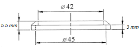
Figure 2: Ring dimensions.
|
Fc % |
C % |
Si % |
Mn % |
P % |
S % |
Cr % |
Mo % |
Ni % |
V % |
Al % |
|
98 |
0.582 |
0.282 |
0.595 |
0.0176 |
0.0267 |
0.0543 |
0.0119 |
0.0573 |
0.01 |
0.0095 |
|
Zr % |
As % |
Cd % |
Cu % |
Nb % |
Ti % |
W % |
Pb % |
Sn % |
B % |
Ca % |
|
0.013 |
0.01 |
0.016 |
0.033 |
0.0374 |
0.0055 |
0.0150 |
0.020 |
0.0068 |
0.001 |
0.0005 |
Table 1: The quantometry analysis for samples.
Samples were tested in the form of 8 treatments and repeated twice in the presence of the control sample as follows.
- Treatment number one: DC nickel solution plating (A) containing 5 grams per liter of saccharin
- Treatment number two: Solution A containing 10 grams per liter of saccharin
- Treatment number three: Solution A containing 5 grams per liter saccharin + calcium carbonate
- Treatment number four: solution A containing 10 grams per liter saccharin + calcium carbonate
- Treatment number five: solution A containing 5 grams per liter saccharin + silica
- Treatment number six: solution A containing 10 grams per liter saccharin + silica
- Treatment number seven: nickel pulsatile solution plating containing 10 grams per liter of saccharin
- For pulse plating, treatment number eight: coating by electroplasma
- Treatment number nine: after cutting pieces without any sample coating operations were prepared to compare with other samples.
Treatments one to six were plated using DC method and the seventh treatment was plated using pulse currents. Thus, a total of 16 coated samples were tested with an uncoated control sample. Selecting treatments were performed significantly considering two levels of saccharin: 5 grams per liter and 10 grams per liter in the watts bath [5]. Samples were polished with 600, 1200 and 2000 sandpaper respectively, and finally with alumina powder. Until, relatively smooth and glossy surface was obtained. After polishing, the samples were coated by DC current plating and pulse plating method (square wave DC current) and a number of electroplasma methods.
2.2 DC plating method
The apparatus for nickel electroplating is shown in Figure 3. The bath composition and electrode position conditions are shown in Table 2.
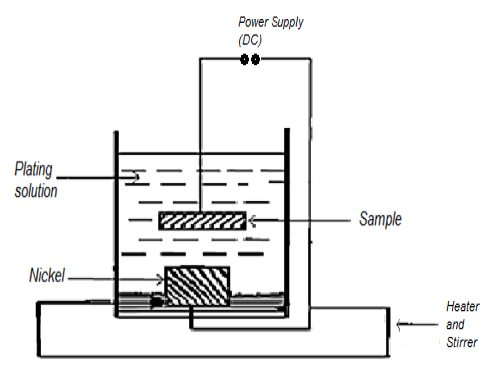
Figure 3: Apparatus for DC plating.
Samples coated from the bath with the composition of Table 2, coating treatments 2 and 1were formed in the presence of 0.5 and 1% saccharin, respectively, treatments 3 and 4 were coated by adding calcium carbonate from beach sand, treatments 5 and 6 were coated by adding silica in the sand of desert.
|
Bathroom contents |
Value |
|
300 |
|
|
45 |
|
|
45 |
|
|
Saccharin |
5,10 |
|
Peak flow density |
3,12 |
|
Bath temperature |
60°C |
|
Total suspension time |
25, 80 min |
|
pH |
3-3.5 |
|
Anode |
Nickel or Graphite |
Table 2: The bath composition and conditions for DC electroplating.
2.3 Pulse plating method
The placement of the sample in a solution was similar to the previous method as shown in Figure 3. The only difference was the source of pulse supply. A computer with special programming and connection-oriented network were used. A special computer program provided the possibility of on and off times of the current with a square wave. Samples were coated by pulse plating according to Table 3.
|
Bathroom contents |
Value |
|
NiSO4, 6H2O |
300 gl-1 |
|
NiCl2 |
45 gl-1 |
|
H3BO2 |
45 gl-1 |
|
Saccharin |
5.10 gl-1 |
|
Peak flow Density |
0.35 ACm-1 |
|
ton |
2.5,5 ms |
|
tof |
2.5,5 ms |
|
Bath temperature |
60°C |
|
Total suspension time |
10,105 min |
|
PH |
3 -3.5 |
|
Anode |
Nickle |
Table 3: Pulse plating conditions.
Saccharin is necessary to use in order to determine the optimum conditions for the production of nanostructured nickel coatings as small as possible. In this study, different concentrations of saccharin and current densities were used. A low time interval (2.5 ms) of current application (ton) for high current density [2 A/cm2] and A higher time interval of current application (5 ms) for low current densities (0/3 A/cm2) were used. The opposite of above situation could be true for lack of applying current (toff). During the plating in every 30 minutes, bath PH was controlled. If necessary, by adding 10 percent sulfuric acid solution was returned to the original range.
Since the bursting of bubbles of revived hydrogen on the cathode surface, cavities were formed on the surface of the coated sample. To avoid this problem, SNAP compound with the concentration of 0.15 was used in the bath. This combination causes the hydrogen bubbles bath to be separated with a mild stirring of the cathode during plating [5]. According to the size and type of sample, the best conditions of on and off of current was 5 ms and 95 ms, in about 105 minutes, the bath contained 10 g. e-1 saccarine. For this reason, coated samples were excluded from the comparison with other treatments in terms of current and change in the concentration of saccharin [9].
2.4 Eletro-plasma method
In this way, a coating was formed on the surface of the objects as a diffusion layer. The source of the supply was two models, the first source of power supply with a maximum current of 100 mA and a voltage of 380 volts that is suitable for coating small objects. The second source of power supply with a maximum current of 100 mA and a voltage of 1000 volts that is for coating large objects.
Table 4: Electro-plasma compounds.
After coating and assessing hardness, the results obtained in Table 5. The composition 2 was used to coat a surface area of 15.13 square centimeter objects. The conditions of the samples in solution and connecting the anode on an iron plate surrounded the sample can be seen in Figure 8. In the Electro-plasma, between the cathode (sample) and the anode, spark occurs and the solution temperature rises to about 2000°C. A semi-cylindrical anode was used to make a better connection, and to reduce Cathode level and current requirements in circle, samples were put in a Teflon coating. To reduce the possibility of generating current, all the objects of the samples in Teflon coating were coated with lacquer.
|
Sample Code |
Hardness Value (HV) |
|
1 |
500 to 700 |
|
2 |
700 to 830 |
|
3 |
200 to 300 |
|
4 |
180 to 250 |
Table 5: Results of assessing hardness.
2.5 Determining the size of grains by XRD method
Determining the size of grains by XRD method was done by using Bruker D8 advance diffractometer device and analyzing in scan speed of 5 0/min, and radiation of Cu.Ka. X`Pert software was used to analyze the XRD spectra. The following equation was used to determine the size of grains. The first part represents the micro-lattice strain at the height of segregation and the second object represents the grain size at the width of the diffraction peak.
= 2 ζ tan θ + 0.9 λ / D cos θ (1)
In this equation, Wf is complete width of half maximum equals FWHM, ζ equals micro-lattice strain, D equals the average size of grains, λ equals the wavelength of the applied radiation and θ is the returned angle. If the Cos θ is multiplied on both sides of the equation (1), then it can be represented as follows:
= 2 ζ sin θ + 0.9 λ / D (2)
By drawing the values of Cosθ Wf based on Sinθ, a straight line can be obtained that its slope is twice the amount of micro-strain and width is equal to a multiple of the average grain size. Samples were installed on the plow blade by electric welding. Since the amount of weight reduction of samples during tillage is the index of wear in this study, as Figure 4 shows a crown on the blades was used to avoid making errors during installing samples till welding points would be done on them and by separating the crown of samples for secondary weighting, do not face with losing or gaining weight arising from the remnants of welding electrodes on the samples.
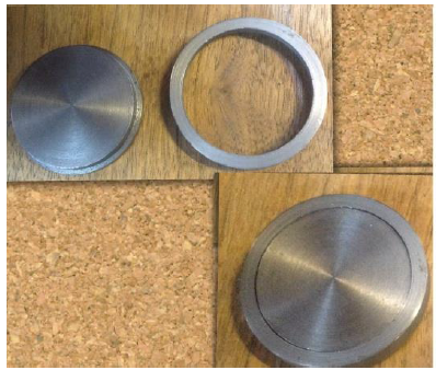
Figure 4: The crown and placement on the sample.
To remove the effects of slope on any blade, the placement of samples have changed as Figure 5. The shapes of L, P, E, S denote the treated samples plated with a DC, pulse and electro-plasma and control methods.
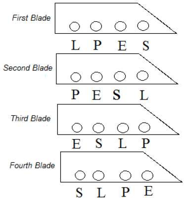
Figure 5: Conditions of samples on tillage.
A tractor made by Iran Co. Model 399 with a power of 65 hp was used to drag tillage in the field. During tillage, tractor moved in the field at a steady pace of 3 mph, with 3 heavy gears. Fields of Shiraz University located in Badjgah at the latitude of 29 degrees 43 minutes 40 seconds of northern and at the longitude of 52 degrees 35 minutes and 1 second of Eastern and height of 1810 meters above sea level, 16 kilometers distance of north of Shiraz were selected. Quartz is one of the most abrasive materials and the most common mineral in nature. The amount of quartz in the soils of agricultural college have been reported in Table 6 [10].
|
Depth (cm) |
The amount of quartz |
|
15 to 50 |
10 to 20 |
Table 6: The amount of quartz in soils of Bajgah.
|
Moisture content (%) |
Porosity (%) |
Apparent density (g/cm3) |
|
14 |
46 |
1.43 |
Table 7: Physical Properties of Soils.
Results and Discussion
In Table 8, the average hardness of each sample is given in terms of Vickers, show the effect of the indenter on the hardness levels of the samples. Figure 6 shows the treatments hardness average value comparison, according to Vickers by Duncan test.
|
Sample code |
Applied force (KgF) |
Hardness Value (HV) |
|
1 |
20 |
280 |
|
2 |
20 |
280 |
|
3 |
20 |
280 |
|
4 |
20 |
290 |
|
5 |
20 |
250 |
|
6 |
20 |
250 |
|
7 |
5 |
480 |
|
8 |
5 |
830 |
|
9* |
20 |
235 |
*control sample
Table 8: Results of assessing hardness.
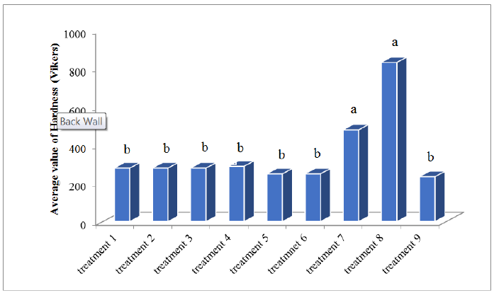
Figure 6: Comparison of the average value of hardness by Duncan methods.
3.1 Results of samples wearness in the field experiment
The weight loss results are shown in Table 9. Percent of Relative wear resistance determined by reverse of losing weight of each sample is multiplied by the percentage. Figure 7 shows the comparison of relative wear resistance by Duncan’s method. Due to the hardness (Table 8) and the amount of wear (Table 9) it was observed that the relationship between hardness and wear is an inverse relationship, as the hardness increased, the amount of wear was also reduced. This is shown in Figure 8 as a comparison chart.
|
Sample code |
Loss weight (gr) |
|
1 |
0.158 |
|
2 |
0.150 |
|
3 |
0.151 |
|
4 |
0.145 |
|
5 |
0.201 |
|
6 |
0.198 |
|
7 |
0.106 |
|
8 |
0.004 |
|
9 |
0.240 |
Table 9: The rate of sample weight loss after tillage.
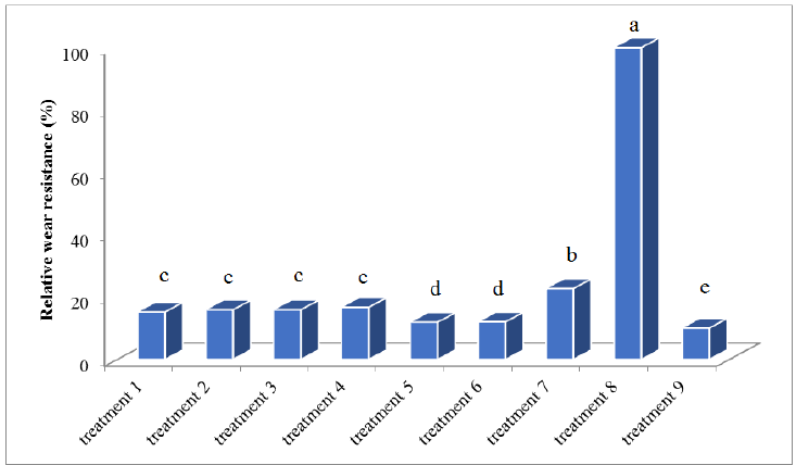
Figure 7: Comparison charts of relative wear resistance to Duncan method.
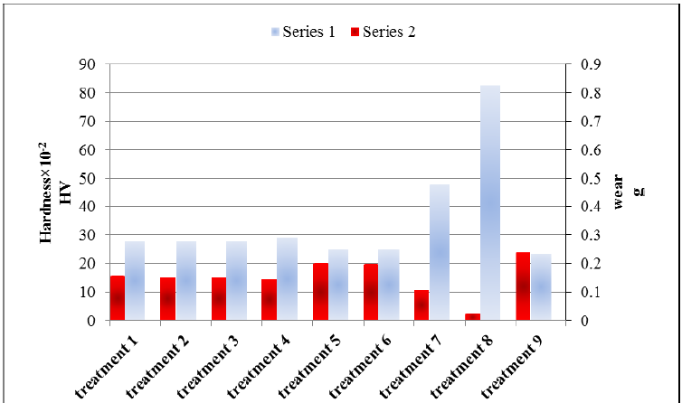
Figure 8: Comparison the average hardness and average wear of each treatment (series 1: Hardness, series 2: Wear).
3.2 The results of SEM and XRD investigation
Figure 9 shows the SEM1 image (SEM) of treatment coating No. 7 and Figure 10 shows the SEM image of treatment coating No. 8, before carrying out wear tests. By comparing the two images, it can be seen that the morphology of the special coating from the electro-plasma methods is so that typically the average grain size and the effect of different coatings cannot be determined with this method.
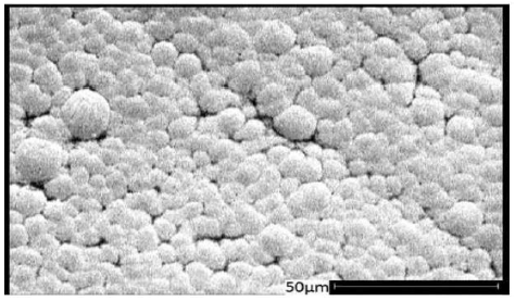
Figure 9: SEM, treatment (7).
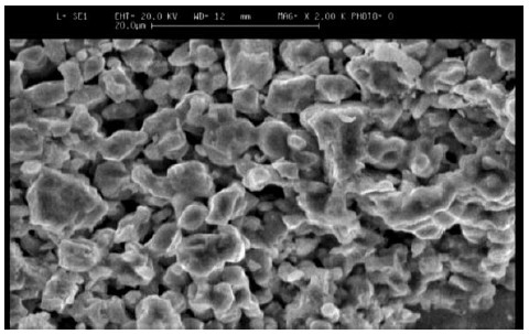
Figure 10: SEM, treatment (8).
Figures 11 to 13 shows the XRD spectra, which were analyzed by X`Pert software. These spectra include information such as substances on the surface, micro-lattice coating, seed size and other data that some of them are shown in Table 10.
|
+0.9λ/D cosθ |
Average grain size (nm) |
Microstrain *10-3 |
|
Y=-2.1*10-3x+3.7*10-3 |
38 |
1.05 |
Table 10: The medium grain size and micro-lattice coating of treatment (7).
PCD-Pulse Current Density; SC-Saccharin Concentration; D-Average Grain Size
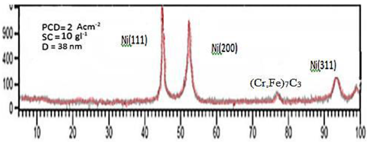
Figure 11: XRD, spectrum of coated samples by using pulse plating (treatment 7).
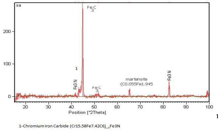
Figure 12: XRD, coated sample No. 4 by electro-plasma method.
1-Iron Nitride (FeN0.0939), (Fe3N), Cementite (Fe3C); 2-Iron Nitride (FeN0.0939), Iron Carbide (Fe7C3); 3-Iron Carbide (Fe2C); 4-Iron Carbide (Fe2C), (Fe3C), Nickel Carbide (Ni3C), Chromium Carbide (Cr23C6); 5-NickelCarbide (Ni3C), marten site (C0.12Fe1.88), Cementite (Fe3C), Iron Nitride (FeN0.088), Nickel Carbide (Ni3C); 6-Chromium Carbide (Cr23C6); 7-Choromium Nitride (Cr2N), Chromium Carbide Nitride (Cr3C (C0.52 N0.48); 8-Iron Nitride (Fe2N); 9-Chromium Carbide (Cr23C6)
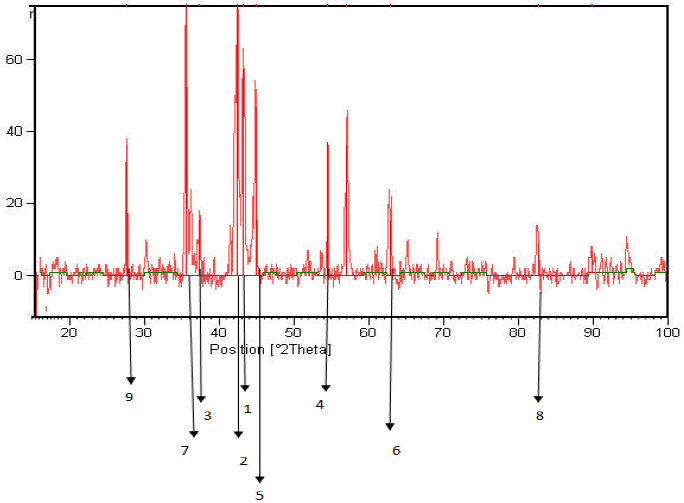
Figure 13: XRD, coated sample No. 2 by electro-plasma method of treatment 8.
Control samples showed the lowest wear resistance, that is the highest level of wear and the lowest level of hardness was related to these samples. In the case of uncoated samples, a wear test was carried out separately, the results showed that without mechanical polishing, the uncoated sample had more wear resistance, it can be concluded that mechanical polishing to make the surface of the sample smooth, reduces the interaction with hard particles in the soil and finally has low weight loss.
Treatments 1 to 6 (samples coated by DC plating) also had differences in terms of the nature of the additives in the solution relative to each other. Generally, they didn’t have significant differences in terms of hardness and wear resistance according to Duncan test. But among this group, the samples which were coated in a percent saccharin solution showed better wear resistance, and this was consistent with the results of Najafi [5]. Adding silica to the solution in treatments 5 and 6 rather than treatments 1 and 2 reduced the hardness and wear resistance, this can be due to uniform corrosion of the coating and making a coating containing an inorganic salts. In treatments 3 and 4, wear resistance was increased by adding silicon carbide to the solution. It was partly because of the nature of silicon carbide and on the other hand, coating structure was formed as a sheet.
Treatment (7) which was coated by pulse plating method showed better wear resistance and hardness compared with samples coated by DC plating method. In this treatment, increasing hardness can be due to more uniform coating and substantially making small grain size compared to the DC plating. However, the expected hardness was not achieved as was expected according to the Najafi [5] that one should achieve 700 Vickers hardness instead of 480 Vickers. The major difference in these two studies were the base metal. Najafi used copper as a base metal in their investigation that is one of the best coating metals. In this study, steel Ck60 was used as the base metal that the presence of chromium compounds created on the surface during plating operations avoided a proper coating of sample and the expected values for the hardness were not achieved.
Since the coated samples did not meet expectations by pulse plating method, electro-plasma method was used for coating the samples. The results were acceptable in terms of wear resistance and hardness of the coatings for using them in a tillage blade. The treatment (8) of this group had the highest level of hardness and in some cases even reached 1000 Vickers of hardness. As XRD analysis of samples showed complex compounds, resistant to wear, on the surface of the coatings. They are considered as intrusive coating group and operations electro-plasma at temperatures over 2000°C and cooling the sample after that was considered as heat treatment. Also, formation of Martensite hard phase in the samples is a good reason to reach such a hardness and resistance to wear.
|
ID |
Average of weight loss (g) |
Weight loss changes compared to uncoated samples (%) |
|
S |
0.24 |
0 |
|
L |
0.167 |
30.41 |
|
P |
0.106 |
55.83 |
|
E |
0.024 |
90 |
S-Uncoated samples (treatment 9); L-Average of coated samples using line plating (treatments 1 to 6); P-Average of coated samples using pulse plating (treatment 7); E-Coated samples using electro-plasma (treatment 8)
Table 11: Comparison of changes in weight loss.
4. Conclusions
The final results can be noted as follows:
- Coating reduces the wear of objects, but different methods of coating create different wear resistance.
- Nickel Nano-structured coatings produced by pulse plating could increase the wear resistance.
- As the average grain size in the coating of nickel nano-structured decreases, wear resistance and hardness increase. The average grain size should be lower than 20 nm to reach a hardness over than 700 Vickers. However, the average grain size of less than 38 nm was not found in the present study. This failure was because of the base metal and generating chromium compounds on the surface of objects.
- Coating produced by Electo-plasma method improved about 90 percent of wear resistance, pulse plating and DC plating improved about 83/55 and 41/30 percent of wear resistance in the samples, respectively.
Acknowledgements
The authors would like to thank the University of Shiraz for providing technical support for this work. The author would also like to thank Prof. Mahzoon for her technical help and support while doing this research.
References
- Shafiee A. Tillage machines. Academic Publishing Center, Tehran (In Farsi) (1995).
- Rabinowicz E. Friction and Wear of Materials". A Wiley-interscience publication. 2nd Edn (1995): 128-132.
- Czichos H. Tribology A Systems Approach to the Science and Technology of Friction, Lubrication and Wear. New York. Elsevier Science Publishing Company Inc (1978).
- Ebrahimi F, Bourne GR, Kelly MS et al. Mechanical properties of nanocrystalline nickel produced by electrodeposition Nanostructured Materials. 11 (1999): 343-350.
- Najafi P. Study of Nick Nano Structural Properties as an Alternative Cover for Chromium Coating. Master’s thesis of Shiraz University (In Farsi) (2008).
- Moore MA, Mclees VA and King FS. Hard facing soil engaging equipment. Agriculture Engineer. Spring (1979): 15-20.
- Owsiak Z. Wear of symmetrical wedge-shaped tillage tools. Soil and Tillage Research 43 (1997): 295-308.
- Yilmaz B. Reduction of wear via hardfacing of chisel plough share. Since Direct. Tribology International 39 (2006): 570-547.
- Mahzoon F. The effect of plasma electronical nitrocarburizing (PEN/C) process on bearing surfaces of hip joint implants. Ph.D. Dissertation of Shiraz University (2009).
- Zareian Gh. Formation, classification and morphological, physicochemical, and mineralogical characteristics of Beyda Plain soils in Fars province, Iran. Ph.D. Dissertation of Shiraz University (1998).
